Electronic circuit design involves ideation, creation, and revision. Learn about PCB Design and the circuit design process

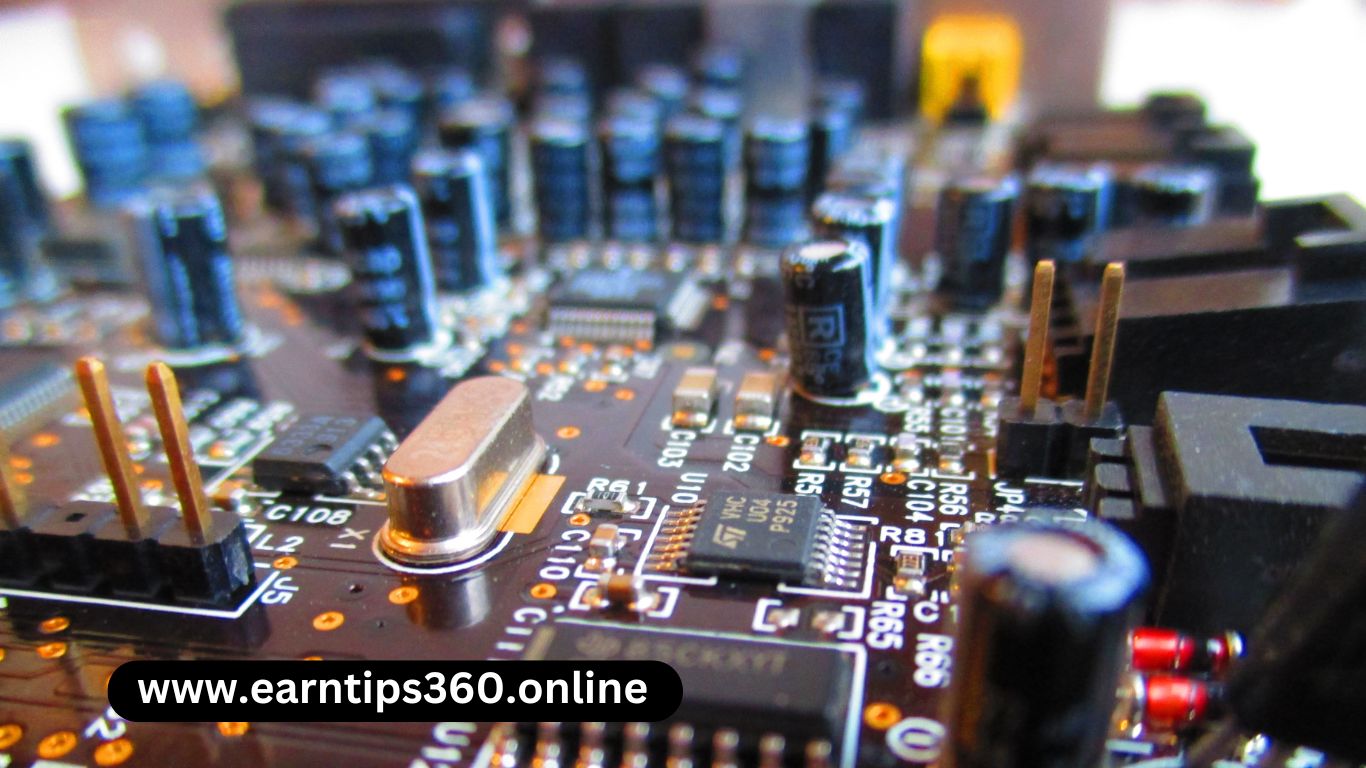
Printed Circuit Boards ( PCBs ) are in every piece of modern electronic equipment, which is why it’s important to know what, exactly, a circuit board consists of and how designers can implement it into so many applications.
Designing an electronic circuit begins on the breadboard (protoboard). The bedboard is a thin plastic rectangular construction base to which electronic components are soldered. The soldered connections components are soldered. The soldered connections are not permanent and can be removed connections are not permanent and can be removed and placed again and within reason it into what is known as a PCB, often used in computations, signal amplification, and data transfer.
The interconnections on a PCB connect the soldered components. Charge flows from the positive terminal throughout the interconnection loops to the negative terminal
The Basics of Electronic Circuit Design

Integrated circuits ( ICS ) have vastly improved metal-oxide-semiconductor field-effect transistors (MOSFET). There are three common circuit designs: analog, digital, and mixed-signal.
Analog Circuit Design
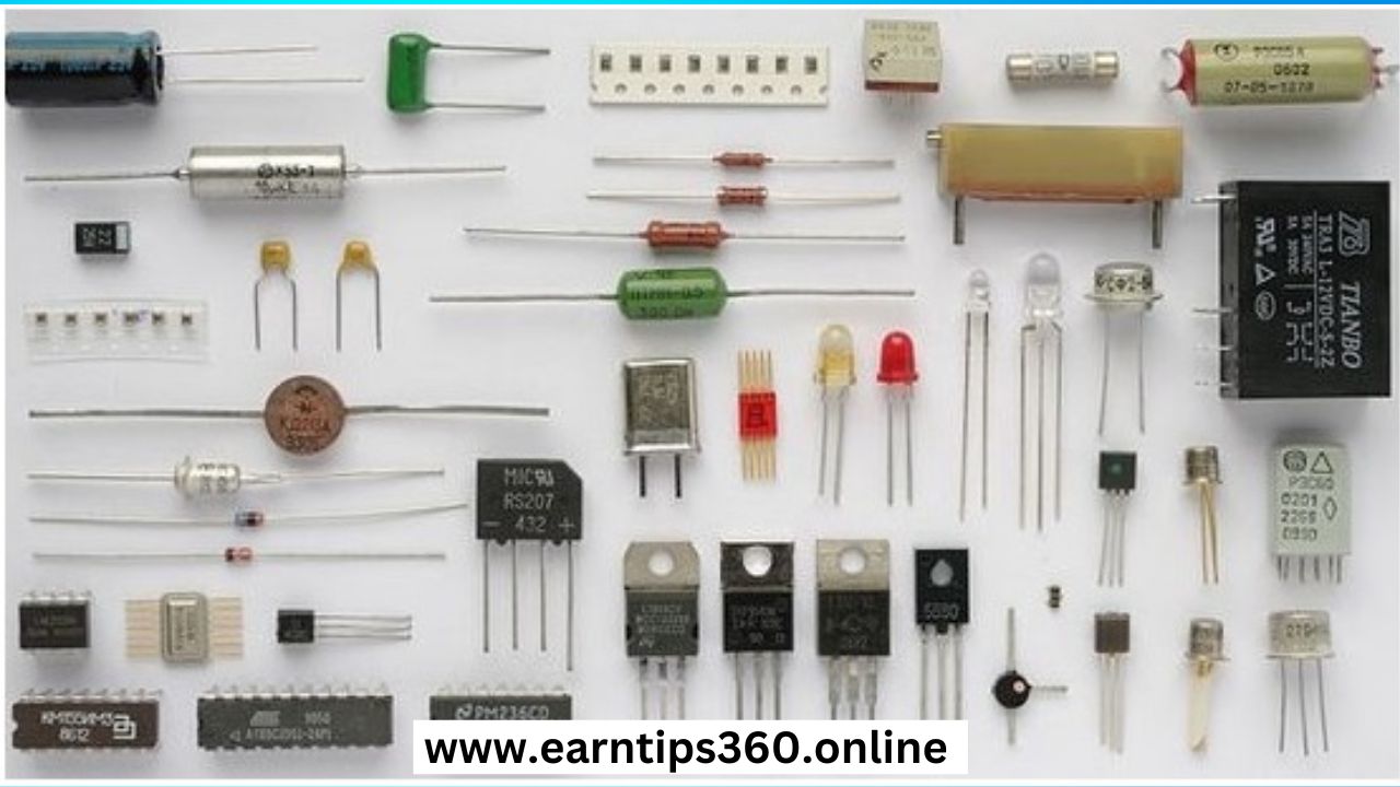
Analog circuit designs generally consist of diodes, transistors, transformers, operational amplifiers, and other passive components. These circuits perform complex data analyses, filtering, and amplification.
Digital Circuit Design
Digital circuit design functions on discrete values ( zeros and ones ). Theses are usually part of the whole PCB design.
Mexed Circuit Design
In many modern applications, PCB designers rarely use just analog or digital circuit layouts. Digital and analog circuits are separated to reduce noise and improve performance.
Microcontroller
Microcontrollers are integrated digital circuits that you can program to perform a variety of commands.
Field Programmable Gate Arrays (FPGA)
FPGAs are digital circuit boards that you can directly configure on a hardware level instead of using a set of instructions. FPGAs are best used for high-performance systems such as aerospace applications.
Schematic Circuit Diagrams
A schematic circuit diagram represents components and interconnections in a PCB layout. These typically use standardized symbols and electrical maintenance.
The Circuit Design Process
The circuit design process is extensive – it involves ideation, testing, prototyping, revising, and retesting. Circuit design goes through several iterations like the writing process begin with an outline or preparation of the idea.
The design process involves moving from the specification at the start to a plan that contains all the information needed to be physically constructed at the end; this happens typically by passing through several stages, although in the straightforward circuit, it may be done in a signal step.
block diagram of the various functions of the specification into a stage the contents of sometimes referred to as a “black box” design. This approach allows the possibly highly complex task to be broken into smaller tasks either by tackled in sequence or divided amongst members of a design team.
Each block is then considered in more detail, still at an abstract stage, but with a lot more focus on the detail of the electrical functions to be provided. At this or mathematical modeling into what is and is not feasible to achieve.
The results of this research may be fed back into earlier stages of the design process, for example if it turns out one of the blocks cannot be designed within the parameters set for it. it may be necessary to alter other blocks instead. At this point, it is also common to start considering both how to demonstrate that the design does meet the specifications, and how it is to be tested.


